
15358968703
Welcome to the official mall of Cloud rolled steel !

Control points of looper in rod and wire rolling
Abstract: looper plays an important role in eliminating the tension between stands in the continuous rolling of rod and wire rod. Poor control of looper will not eliminate the tension, but will increase product defects and steel stacking accidents. This paper summarizes the common faults and control methods of looper, which is very helpful to reduce accidents and improve product quality. Key words: looper control points foreword: continuous rolling is widely used in the rolling of rod and wire rod. In order to eliminate the tension between stands, stabilize the rolling and ensure the size of finished products, it puts forward higher requirements for looper control. Through a large number of production practices and repeated comparisons, the common control methods of looper and how to quickly troubleshoot looper faults are summarized, so as to make the tension appropriate, the size of finished products stable and reduce the steel stacking of looper.
1、 The tension between upstream racks is large, and the looper reacts
If the tension between frames upstream of the looper is too large, the tension between frames of the looper is appropriate. The jacketed height will fluctuate from high to low, as shown in Figure 1-1 jacketed height trend chart, and a big jacketed at the tail section. Point a is the big jacketed tail; The looper adjustment amount will also have a corresponding similar swing, as shown in Figure 1-2 trend chart of looper adjustment amount; See Fig. 1-3 for the current trend diagram. On the finished product, the size of both sides fluctuates, and the size of the tail is hypertrophy, especially
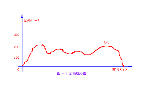
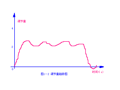
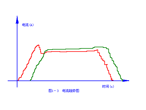
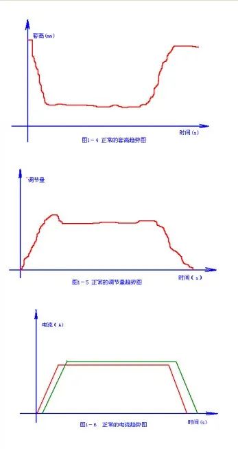
The "neck" part is thin on both sides. Adjustment method: do not only adjust the tension of the looper Bay frame. If the red steel tail is easy to pile up a large set of steel at the looper, first adjust the tension between the frames at the upstream of the looper, and make the tension appropriate in combination with the current trend chart and the state of rolled pieces entering the mill, and then adjust the tension of the looper Bay frame. Finally, the set height trend chart, looper adjustment amount trend chart and current trend chart are in the States shown in Figure 1-4, figure 1-5 and figure 1-6 respectively.
2、 Adjustment of tension between loopers
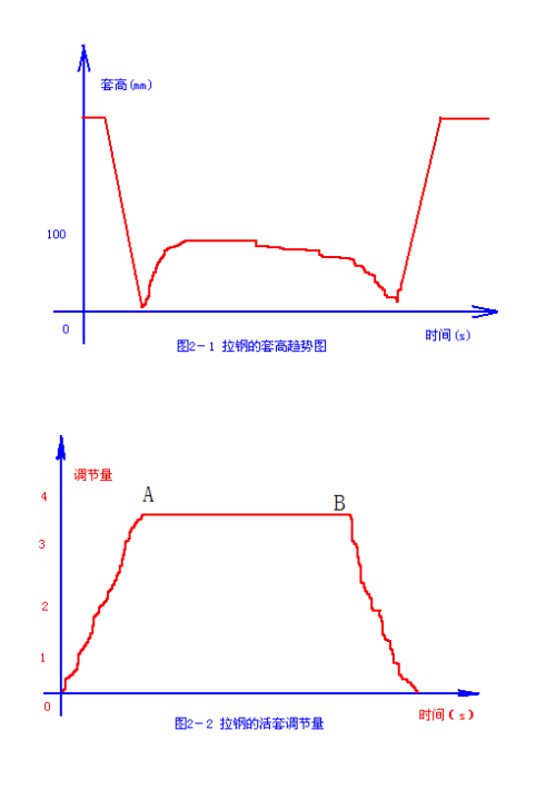
a) If the looper tension between frames is too large, the pushing roller will not start; When the tension between frames is large, the looper can not eliminate the tension, and it will cause great damage to looper equipment. The following is the judgment method for large looper tension: first, visually observe the lifting of the looper, and first ensure that the pushing roller rises; Second, judge and make accurate adjustment through the comparison between the casing height trend chart, the actual display of casing height and the set value display of casing height, or the trend chart of looper adjustment amount and the display of adjustment amount. Here is a summary of the typical causes of high tension between loopers: the trend of looper height is shown in Figure 2-1, and the trend of looper adjustment amount is shown in Figure 2-2. In Figure 2-2, AB reaches saturation state, and the adjustment amount reaches the upper limit.
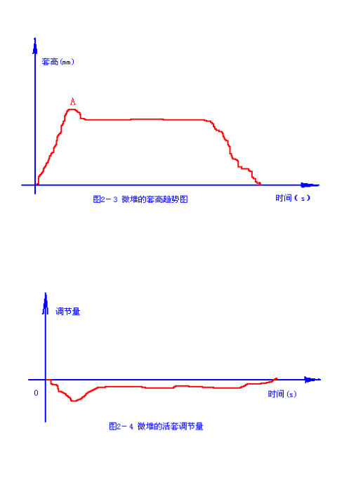
b) The following are generated during the rolling of looper stacking steel: trend chart of looper height 2-3, trend chart of looper adjustment amount 2-4. Point a in Figure 2-3 is the large sleeve produced when red steel just bit the downstream rolling mill of the looper; The adjustment value in Figure 2-4 is negative, and the rolling can still be carried out smoothly at this time. However, the looper failure caused by the non photosensitivity of the looper scanner or other reasons forces the looper to fall suddenly, and there is no doubt that there is a steel stacking accident between the loopers. Therefore, this situation should also be avoided in the rolling process.
3、 Common current trend generated by looper
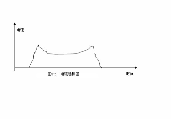
The current trend in Figure 3-1 is generated by a rolling mill upstream of the looper (for example, K3, K5, K7 of the first rolling mill) if the looper is normally lifted. It means that the angle of looper scanner is too low; No matter how much the set height value is, the actual value is always lower than the set value. As long as the looper is set together, the speed of the upstream mill will be reduced, and as soon as the looper is set, the speed of the upstream mill will be increased. It will make it difficult to find the thin on both sides of the finished product. If the dimensions on both sides are found by force, it is easy to pile steel at the head and tail of the finished product and the front of the finished product, especially at the tail. It is almost impossible to find the dimensions on both sides when the tail of the finished product and the front of the finished product are not piled. In this case, the steel shall be stopped in time, and the electrician shall lift the head of the looper scanner to the appropriate position. The dimensions on both sides will then be normal, and the accident rate will be greatly reduced.
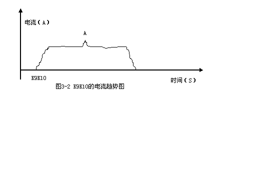
In Figure 3-2, the current of k10k9 has an upward spike at point a, indicating that the looper is slightly pulled, which is the state we want, and it belongs to normal looping.
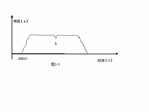
In Figure 3-3, the current of k10k9 has a downward peak at point a, which indicates that the looper micro pile is easy to die when the scanner is not sensitive. Therefore, to avoid this situation, reduce the linear speed of the upstream frame of the looper or increase the set value of the looper height appropriately.
In Figure 3-4, there is a point a with a downward peak and a point B with a upward peak in the current of K9, which indicates that the steel pulling of a looper is serious, but the looper can still be lifted normally. If the looper is the looper closest to the finished rolling mill, the size of longitudinal bars in the second section of the finished standard bar will be low, and even there will be no bars on both sides of the first few meters of the second section of the standard bar, and the length of the second section of the standard bar is the shortest compared with other standard bars (generally 20 to 40cm). To increase the linear speed of the upstream frame of the looper and appropriately reduce the setting of the looper, this defect can be solved by eliminating the downward peak of K9 current point a.

Conclusion: This paper summarizes the typical set height trend chart, looper adjustment amount trend chart and current trend chart from three aspects, and explains their relationship with the quality of finished rod and wire rod and the change of some defects. It provides an intuitive and systematic reference basis for operators, and can effectively help operators find and solve problems more timely and accurately. It provides a reference for operators' experience exchange and new workers' learning.


Gather industry trends
 15358968703
Gather industry trends
15358968703