This paper mainly introduces the structure, working process and the problems existing in the actual production process of the high line automatic baler and their solutions.
1. Overview
PCH 4KNA type baler introduced from Sweden SUND-BIRsta company, automatic baler is an important equipment of modern high-speed wire production line, set mechanical, hydraulic, electrical control as one, with accurate action, reliable, small maintenance, low failure rate characteristics, it is located in the finishing area of high line, Pack the reels from the C-hook coming out of the reel collecting station. This paper introduces the structure and function of the automatic baler and summarizes the common faults and solutions in the actual production process.
2. Working process of baler
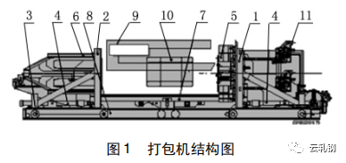
1- Pressure plate 1; 2- Platen 2; 3- Wheels; 4- Hydraulic cylinder;
5- Hit the head; 6- Wire guide system; 7- lifting platform;
8- Guide device; 9-C hook; 10- Reel; 11- Wire feeder
1) Start pressing: the two pressure plates move towards the wire coil at the same time, the buffer used for the wire guide system is pressurized with air in the out position, the two pressure plates begin to move forward on the lower pressure plate pushed by the transverse cylinder, and the lifting platform begins to rise until the wire coil on the C-hook is just lifted;
2) Compaction: When the clamping device moves to the position close to the coil (pre-pressure), the photocell sends a signal to raise the lifting platform to the top position, so that the coil is completely free from the C-hook, its top position is displayed by the pulse generator S9, platen 1 and platen 2 continue to press the coil, when the coil system reaches the platen and compresses the buffer, A movable wire guide slot is displayed by the proximity switch to close the wire guide system;
3) Start feeding the wire and press it firmly in place: close the wire guide slot and start feeding the wire. Platen 1 and Platen 2 compress the coil completely and do not release it until the coil is wrapped. A pulse generator is installed on each clamping plate to control the symmetrical clamping position, so that the coil is returned to the center position of the C-hook;
4) Stop feeding wire, wire end clamp: feed wire wheel through the wire guide system until the wire end reaches the beater head, the wire end reaches the mechanical stop block of the clamping mechanism to stop feeding wire, wire end clamp. The packing line is pushed out of the bend rail, and the approach switch S2 does not work;
5) Wire drawing: the wire guide slot is opened, the wire end is clamped, the timer signal starts, the packing mechanism moves from the feeding position to the packing position, the feeding wheel is reversed, and the packing line is pulled around the wire coil and the stopping wheel.
6) End of pulling wire, torsion: when the packing wire is wrapped around the end of the pulling wire, the feeding wheel stops rotating, and the pulser S9 shows the end of the pulling wire. Start swinging and twisting. When the torsion is finished, the wire clamping is loosened, the wire is cut, and the packaging is finished.
7) Return to the original bit: When the packaging is finished, platen 1 and platen 2 return to the original bit, which is displayed by approaching switches S and S6. The wire guide system is returned to the original bit, which is displayed by the proximity switch S4. The lift is lowered to the original position, which is displayed by the proximity switch S10. In this way, the finished coil can be transported out of the baler and wait for the new loose coil to be packed.
3 Common faults and solutions of baler
In the process of using the wire baler, there are often failures. The following part analyzes the common failures.
3. 1 Tie the head knot wheel knot failure
Because the packaging line used has not been pickled, the packaging line has more oxidized iron. In the packaging process, the oxide sheet is very easy to accumulate at the knot wheel, resulting in the knot in place close to the switch often signals, and the knot wheel does not stop. In this way, we have to stop the car for a few hours to clean up the baotou, affecting the normal production rhythm, causing major hidden dangers to people and equipment, and now the mechanical travel switch is installed on the outside of the Baotou to avoid similar accidents.
3. 2-card wire
1) Double-slot gland card
After the head of the packing line passes through the moving cutting edge, it will often get stuck at the double groove gland. The reason for the stuck line is that the gap between the swing shaft of the kinker and the body of the head is large. After the end of the kinker, the kinker and the body of the head are relatively rotated, resulting in the packaging line being wrongly guided and stuck when it is threaded through the kinker gear again.
Treatment method: A special wear-resistant adjusting pad is installed between the swinging shaft and the body of the beater head, and the gap is adjusted to the range of 0.18mm, which greatly reduces the relative rotation between the kinker and the body of the beater head, so that the packing line can smoothly enter the double-slot gland through the kinking gear, and avoid the card line.
2) Line path card line
After the localization of movable track spare parts, due to the limitations of domestic processing accuracy and domestic materials, the center line of the baotou outlet and the outer track entrance, the inner track exit and the center track entrance cannot be aligned after the installation of the spare parts, resulting in frequent clamping of the packing line on the outer track and the center track.
Solution: When installing the track, align the outer track of the active track with the center line of the outlet track of the baotou head, and adjust the outlet of the inner track with the pad, so that it is aligned with the center line of the center line; At the same time, the gap between the support wheel of the track and the slide of the track is adjusted to the range of 3 mm.
4 Conclusion
Through the modification and adjustment of some parts of the baler, the jamming and kinking faults are avoided, the operation rate is increased, and the accident time is reduced. It provides guarantee for high rhythm wire production line.


 15358968703