ENCYCLOPEDIA

Analysis and improvement of seam adjustment and misalignment of flat/vertical conversion mill

Abstract:Due to the particularity of the use of the flat/vertical converter, the design, manufacture and use of the rolling mill have higher requirements in the actual use of the site, if the design and manufacture are not considered, improper use, it is easy to have problems, which has a significant impact on the quality of the product. This paper introduces several problems exposed in the field use of the imported flat/vertical conversion mill in the continuous rolling line and the measures to solve these problems.

1. Structure and working principle of flat/vertical conversion mill

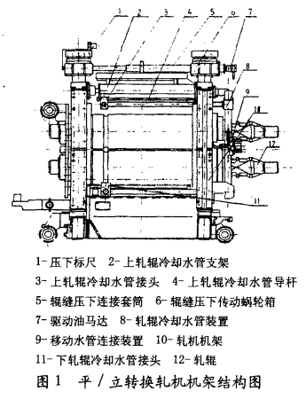
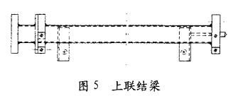
As the name suggests, the horizontal/vertical conversion mill can be used as a horizontal mill or a vertical mill can be used at 90° to meet the requirements of the continuous rolling production process for a certain mill layout. Due to the two different process layout requirements, the structure of the vertical conversion mill stand is different from that of a single flat mill and vertical mill, as shown in Figure 1.

(1) When the rolling mill of this model is used as a flat mill, the quick frame changing device directly pulls the rolling mill onto the rolling line, the horizontal cardam sleeve is directly connected with the roll (part 12) head (good locking device), and the mobile water pipe connecting device (part 9) of the cooling roll is connected with the fixed water pipe joint. When the hydraulic anchor bolt is locked and the roll gap is adjusted, steel rolling can be carried out (see Figure 1).
(2) When this type of mill is used as a vertical mill, the mill first needs to be turned over 90° on the rack turning device, and then the mill is hoisted onto the quick rack changing device by the crane. The horizontal hydraulic pull-push device directly pulls the mill onto the rolling line, and the vertical cardam shaft sleeve is directly connected with the roll head. The moving water pipe connecting device (Part 9) of the cooling roll is connected with the fixed water pipe joint, and the lifting device pulls the rolling pass center of the mill to the rolling center line, the hydraulic anchor bolt is locked, and the roll gap is adjusted to roll steel.
The mill is characterized by the use of rubber springs to balance the weight of the roll system.
 
2. Two main problems in field use
(1) the roll gap of the mill cannot be adjusted. The situation reflected on the scene is mainly that the roll gap of the roll can not be adjusted at all, the roll gap adjusting mechanism is removed and disintegrated, and it is found that the regulating screw and the wire master have been locked.
(2) When the vertical mill is used, the relative position of the two rolls changes, that is, the phenomenon of wrong rolls (pass asymmetry) occurs. The site production workers reflect that the position of the roll often changes, and after the symmetrical position is adjusted, the production time changes again, and qualified steel can not be rolled.

3. Reason analysis

      (1) The first problem, through analysis, the main reason is due to the long-term production and use of rubber spring (part 8) aging, the thickness and elasticity of rubber spring are reduced, the balance force is greatly reduced; This creates a gap between the spherical pad (part 12) and the copper nut (part 11). Due to the existence of the gap, the alternating rolling force of frequent steel rolling produces a great impact between the spherical pad and the copper nut. The effect of the alternating impact force makes the internal thread fatigue fracture of the copper nut no longer exist between the screw and the nut, and the huge inlaying force between the screw and the nut makes the screw parts unable to rotate, resulting in the roller gap cannot be adjusted.
      (2) Through analysis, the second problem is mainly caused by the fact that when the rolling mill is used as a vertical mill, the overall deformation of the bearing seat and the frame of the rolling mill after being stressed is shown in the figure due to the ill-considered design. The connection between the two roll frames designed by the external side only relies on the upper and lower beams of the inlet and outlet guide, and the connection between the upper and lower beams of the guide and the frame is the realization of the friction generated by bolt pretightening. When the mill is used in a vertical mill, since the lower bearing seat is the restraint end, the friction provided by all the vertical downward force beam fastening bolts is much less than that provided by the force acting almost exclusively on the lower roll frame, which is equivalent to a cantilever beam (as shown in Figure 2). Theoretical analysis is as follows (the upper roll frame deformation is small, deflection Y1,Y2 can be ignored)
F1, F2 - the weight of the upper and lower roll assembly and the cardan shaft system; F3 Weight of roll frame, tie rod and guide device; F4 - the upper roll gap adjusts the weight and weight of the worm gear box; Y1 - deflection of the lower roll pass position on the water surface; Y2 - the deflection of the upper roll pass position on the horizontal plane.
The deflection formula of the cantilever beam after stress is
Shizhong
Elastic modulus E=200GN/m²
The rectangular moment of inertia J=b*h³/12
For the roll frame structure (see Figure 3), its moment of inertia Jz=2 (B/H³/12-b*h³/12)
By inserting the geometric dimensions in Figure 3 into the above formula, we get Jz=C.0002208m⁴
Use equation (1) to calculate the deflection:
Deflection Y11=-1.528mm caused by F1=12t
Deflection Y12 caused by F1=12t =-0.3233mm
Deflection Y21 caused by F2=12t =-0.647mm
Deflection Y22=-1.007mm caused by F2=12t
Deflection Y31=-0.6056mm caused by F3=8.4t
Deflection Y32=-0.148mm caused by F3=8.4t
Deflection Y42=-0.3946mm caused by F4=1.7t
Deflection Y42=-0.0747mm caused by F4=1.7t
It can be obtained by using superposition method
Y1 = Y11 + Y21 + Y31 + Y41 = 3.1752 mm
Y2 = Y12 + Y22 + Y23 + Y42 = 0.6467 mm
Delta Y1 = Y1, Y2 = 2.5282 mm
△Y=-2.5282mm is the staggered roll value on the horizontal plane of the upper and lower rolls of the mill after the mill has turned 90°.
If the wrong roll value of △Y=-2.5282mm exists in the primary rolling area and there is room for adjustment, then it is absolutely not allowed to exist in the finishing rolling area, which will lead to the rolled steel becoming waste.


4. Solution measures
(1) The cause of the first problem has been found, and the measures to solve the problem are: the inspectors should often go to the production site of the rolling mill to observe the amount of roll bounce during the production process, if the amount of roll bounce is very small, it means that the elasticity of the rubber spring is still very good, the balance force is large, and the gap impact between the spherical pad and the copper nut will not be caused. If the amount of spring of the roll is large, it means that the elasticity of the rubber spring is insufficient, which will cause a huge impact between the spherical pad and the copper nut and damage the copper nut rubber spring.
(2) The main reason for the second problem is that there is not a rigidly connected beam designed between the two roll frames, resulting in the rolling mill movement frame not forming a rigidly closed frame. The solution is to remove the original support beam of the upper roll cooling water pipe (part 2 in Figure 1), and its structure is shown in Figure 4; In its original position, a rigid coupling beam (see Figure 5) is designed and manufactured, which still has the function of a water pipe support. Through such a change measure, when preparing to change the roll in production, the trouble of tightening a few bolts is more, but the fatal problem is solved, and the result of using the rolling mill online proves that the effect is good.
2023/10/08 09:17:53 212 Number