
15358968703
Welcome to the official mall of Cloud rolled steel !

Coil Control Analysis of Hot Rolled Strip
Abstract: The coil shape of hot-rolled strip is an important factor affecting the quality of strip. Aiming at the coil shape problem in the hot-rolled strip coiling process, this paper analyzes and studies various coil shapes from the aspects of control model, process operation, equipment management factors, etc., so as to solve the problem of bad coil shape and improve the yield. and economic benefits.
1 Introduction
Coil shape is an important and difficult to control item in the coiling area. If a problem occurs, it will affect the normal operation of the subsequent process, and in severe cases, it will cause a short-term unplanned shutdown of the main rolling line. When the coiled tower shape is within the handleable range, it can be processed by finishing lines such as flattening line, rewinding line, cross-cutting line, etc., but additional costs will be added. , The walking beam falls off the roll, smashes the equipment, and affects normal production in serious cases.
2 Roll defects and their causes
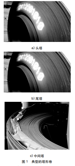
The main defect of poor roll shape is the tower shape. According to the type of tower, it is divided into three types: inner tower (head tower), outer tower (tail tower), and middle tower (interlayer dislocation, sawtooth). Typical poor roll shape as shown in Figure 1.
1) Inner tower: The inner ring of the head is seriously biased to one side, forming a tower shape. Due to the serious deviation of the incoming material or the camber bend of the strip head, the side guide plate is clamped to correct the deviation, and the center line is adjusted back, resulting in a tower shape. Severe wear on one side of the helper roller or poor levelness will also aggravate the generation of the tower shape.
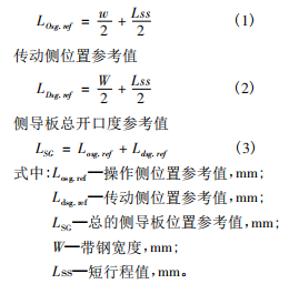
2) Outer tower: Within a dozen circles at the tail, the strip is biased to one side, forming a tower shape at the tail of the coil. After the end of the strip exits the finishing stand, the pressure deviation on both sides of the pinch rolls becomes larger, and the side guide plates cannot hold the strip, causing the center line to deviate and form a tower shape.
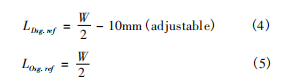
3) Intermediate tower: The strip in the middle part of the coil is crossed on both sides, and the two sides are not smooth and look like sawtooth. Due to the large tension fluctuation between the finishing stand and the coiling pinch roll and the speed mismatch, the strip steel runs unstable, the clamping force of the side guide plates is insufficient, and the strip steel wanders between the side guide plates and shakes up and down. . According to the reasons for the tower shape, it can be divided into equipment reasons, process reasons and operation reasons.
2.1 Equipment reasons
1) The side guide plate has large deviation and serious wear and tear, resulting in the inability to hold the strip steel and resulting in a tower shape;
2) The levelness of the pinch rollers is not good, the wear is serious, the roller gaps on both sides between the upper and lower rollers are inconsistent, and it is easy to generate a tower shape during coiling;
3) The level deviation of the help roller and the reel is large and the wear is serious, resulting in a large gap between the two, so that the head of the strip cannot pass through the help roller in parallel, resulting in a tower shape;
4) The level of the rollers of the unloading trolley is not good, and a tower shape is formed when the tail is fixed; after the fixing of the tail is completed, the idler can not be locked, and the steel coil slips on the trolley, which will easily cause the tower shape; abnormal timing control of the unloading trolley will also cause a tower shape. tower;
5) Detect original distortion or abnormality. When the head reaches the pinch roller during production, the system does not detect the load signal and does not send a signal, or receives the load signal, but the analysis and processing time is too long, resulting in the construction sequence (roller opening, reel diameter expansion) Error and abnormal timing of the second short stroke action of the side guide;
6) Unstable equipment operation: poor position accuracy, hydraulic thin oil system failure, inaccurate calibration, etc.;
7) Unstable electrical operation: incomplete transmission chain protection, unstable transmission, failure of control components, abnormal data transmission (torque, tension, position, pressure, speed, coiling temperature, tracking, etc.), abnormal control logic, etc.
2.2 Process reasons
1) Problems of incoming materials for finishing rolling: Tower shape will be generated due to serious deviation, sickle bend, S bend, abnormal convexity, large wedge shape, wave shape, and low coiling temperature;
2) The control sequence of the side guide plate, the inconsistent movements on both sides will cause the head of the strip to hit the slow side of the side guide plate, resulting in a tower shape;
3) The opening degree of the side guide plate is not properly set, the thin specification is fast, the movement speed of the side guide plate is constant, and the opening degree is set too large, the operation time is too long, and it is easy to produce a tower shape.
2.3 Reasons for operation
1) The data given is not suitable, such as lead rate, lag rate, tension, etc. will produce tower shape;
2) The equipment inspection is not timely and the equipment replacement is not timely;
3) Poor skills, failure to operate in accordance with regulations, misoperation, untimely monitoring, untimely adjustment, etc.
3 Ways to improve
Equipment and operational reasons aside, this section focuses on process improvement measures.
3.1 Setting and control of side guide opening
The side guide plate is located in front of the pinch roll of the coiler, and is mainly used to guide the strip into the pinch roll and to center and clamp the strip to ensure the stability of the coil shape. Side guide control is divided into two control modes: pressure control and position control.
3.1.1 Opening degree setting
It is mainly divided into the following five stages: Standby: XSG = B + S1 where: XSG: computer setting value of the side guide, mm; B: target width of the strip, mm; S1: one short stroke, generally S1 = 100mm.
1) After the head of the steel strip is detected at the entrance of the guide plate, the two sides are closed symmetrically to 30mm from both sides of the guide plate. XSG = B + S2 (S2 = 30mm);
2) After the strip head reaches the pinch roller, the signal is detected to activate the second short stroke, the short stroke hydraulic cylinder starts to move, and the guide plate is closed to fix the strip until the post tension is established;
3) After the back tension is established, in order to prevent expansion and contraction, the position of the operation side guide plate should be fixed, and the transmission side guide plate should be moved to the measured width position. The pressure control is realized by adjusting the position of the side guide plate on the transmission side;
4) When the tail of the strip enters the pinch roller, it returns to the standby setting value.
3.1.2 Control sequence of side guides
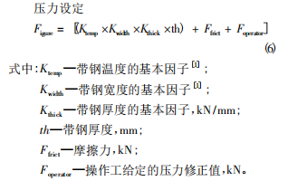
In order to avoid position jumping, all the setting values are slowly approached according to a certain slope. Manual intervention and the set slope are stored in internal parameters and can also be varied. These settings are limited by the large and small positions of the hydraulic cylinders. If no operating mode is preselected, the current position of the side guides is regarded as the set value. In automatic position mode, the reference opening on the operating side of the entry side guide is the actual strip width plus the short strokes on the operating and drive sides. This short stroke is applied as an added value if there is no strip between the side guides.
Once the strip head enters the pinch rolls, the operating side closes to half the strip width and then maintains position control. This drive side position setting will become half the strip width minus an adjustable value (10mm). If the transmission side touches the edge of the strip, the actual pressure increases to a value, when this value is higher than the set pressure value, the side guide will automatically control the pressure to the calculated pressure. In the process of the pressure control sequence, the set pressure value will be adapted according to the deviation of the actual pressure on the operating side and the transmission side. If the strip builds up a lateral force with the drive side, the actual pressure detected on the operator side will decrease and the deviation from the set pressure on the drive side will increase. Under the pressure control, the deviation between the actual position and the set position is controllable during the guiding process of the side guide on the transmission side. If this deviation exceeds the calculated value (the guides wrinkle the strip), pressure control is not available and the side guides will be position-controlled and open to half the width of the strip.
When the thermal check before the strip tail leaves the side guide and a time delay is added, the side guide will open for a set short stroke. When the end of the strip enters the thermal detection area before the pinch rolls, the side guides will prepare for the next piece of steel.
3.2 Pinch Roller Control
According to the pressure deviation on both sides of the pinch roller, the operator can adjust the pressure on both sides after the tail is thrown, so as to prevent the deviation of the strip caused by the large pressure deviation on both sides, and adjust the pressure on both sides in advance to improve the roll shape.
3.3 Winding tension setting
The coiling tension has a great influence on the roll shape. Tension setting: T = w × h × t where: T - total tension, N; w - finished product width, mm; h - finished product thickness, mm; t - unit tension, N/mm2, the unit tension is based on the secondary system According to the calculation by the method of look-up table, the thickness of the strip steel is different, and the unit tension is also different. If the tension setting is too large, the strip will be partially stretched and narrowed. Exceeding the standard will cause the subsequent process to recoil and cut off the narrow part, which will affect the yield and increase the cost. If the tension setting is too small, the winding will not be tight, and the roll shape will be bad to form bread rolls and flat rolls. The program is set to have a small initial tension before uncoiled steel, and to coil with constant tension after the sheet is established. When the tail of the strip reaches F3, the tension reduction control of the throwing tail is used (-20% to -40%) to avoid the unstable operation of the tail of the strip due to the large change of the throwing tension of the last frame. The strip tail runs stably with a small tension until the coiling is completed.
3.4 Setting of lead rate and lag rate
Adjust the lead rate and lag rate according to the roll shape of the head and tail of the scene. The lead rate needs to be increased if the head roll is not tight, and the lag rate needs to be increased if the tail is loose and the roll is not tight. Data given:
1) The heat output roller table is given 10% to 25%, and the speed is increased step by step according to the roller table segment control speed. The hysteresis rate is generally given at 10% to 20%. The thinner the strip, the greater the hysteresis, and the closer the deceleration point is to the coiler; the thicker the strip, the smaller the hysteresis, and the closer the deceleration point is to the finishing stand;
2) The lead rate of the pinch roller is 5% to 15%, and the lag rate is 5% to 10%;
3) The lead rate of the helper roll is 10% to 35%;
4) The roll lead rate is 8% to 20%.
4 Equipment maintenance, electrical optimization, standardized operation
Improve analysis of causes and actions, starting with regular equipment maintenance, electrical optimization and planning operations to ensure volume control.
4.1 Equipment maintenance
Regular maintenance of equipment to ensure equipment accuracy. 1) The position deviation of the side guide plate is ± 2mm, the wear amount is within 5mm, the alignment deviation is ± 2mm, and the gap between the side guide plate and the roller table is less than 3mm; 2) The position deviation of the two sides of the pinch roller is 1mm, and the positioning accuracy of the roll gap is ± 0.1mm, horizontal Deviation ± 0.2mm, pressure deviation ± 10kN; 3) Roller tail setting accuracy ± 0.1mm, pressure deviation ± 5kN; 4) Reel: retraction position 727mm, initial expansion position 745mm, final expansion position 770mm.
4.2 Electrical optimization
1) When the trigger signal of the pinch roller does not act abnormally, the side guide plate can be started after a few seconds of short-stroke action set in the program, so as to avoid the tower shape caused by the second short-stroke inactivity;
2) Optimize the tension correction program, add and subtract tension on the operating table, and control each adjustment at 5% of the unit tension;
3) The tail pressure of the helper roller is optimized. When the tail reaches the side guide plate, the selected end pressure helper roller will be pressed against, and the pressing pressure can be adjusted to prevent the tail tower from being stuck on the strip due to excessive pressure;
4) The timing of the unloading trolley is modified. F3 throwing steel rises once, F7 throws steel rises twice, and when the tail enters the side guide plate, it rises to withstand the steel coil, which avoids the loose ring phenomenon caused by the uncontrollable roll of thick and hard specifications;
5) For some important inspection originals, the double original inspection method is adopted to avoid a single failure affecting the operation of the equipment.
4.3 Operating Specifications
1) Inter-professional technical exchanges and learning to improve automation control theory and practical theory. Improve operation skills and reduce abnormal volumes caused by human causes;
2) Formulate spot inspection operation standards, and focus on the inspection and maintenance of some important inspection components and apply what they have learned;
3) Formulate the replacement cycle of process parts, and make records of replacement, inspection and adjustment with the machine repair professional, and do a good job of initialization.
5 Conclusion
Coiling is a process behind the hot rolling line. By taking corresponding measures, the abnormal coil rate can be reduced and controlled, the cutting loss of abnormal coil processing can be reduced, and the product yield and economic benefits can be improved.


Gather industry trends
 15358968703
Gather industry trends
15358968703