
15358968703
Welcome to the official mall of Cloud rolled steel !

Basic knowledge of looper in high-speed wire mill
Looper
In order to ensure the dimensional accuracy of products, modern high-speed wire rod mill adopts micro tension and non tension rolling to eliminate the tension fluctuation caused by various dynamic disturbances in the rolling process and the size fluctuation of rolled pieces. Due to the collective drive of the finishing mill, the finishing mill adopts micro tension rolling. The micro tension value is guaranteed by the fixed speed ratio and the given hole and groove area of each stand. The speed ratio will not change due to control, and the rolled piece area will fluctuate due to the fluctuation of the incoming material area. In order to reduce the size fluctuation of the finishing mill caused by the tension change, several loopers are set up in the pre finishing and intermediate rolling units in front of the finishing mill to eliminate the interference of the dynamic speed change of each stand in the continuous rolling and ensure the precision of the rolled piece.
Definition and function of looper
The speed of adjacent racks is adjusted by the automatic control system to generate "redundant" rolled pieces between racks. The "redundant" rolled pieces form a sleeve shape which can dynamically maintain an arc with the help of the sleeve lifting device. This sleeve shape is called a looper. The looper control function is applicable to the occasions with small section and fast rolling speed. It can eliminate the interference of the dynamic speed change of the continuous rolling stand and ensure the precision of the rolled piece. The looper can realize tension free rolling. The so-called tension-free rolling means that in the rolling process, there is no steel pulling relationship between stands, and it is realized by changing the looper storage. When the rolled piece between two adjacent stands is pulled, the set amount is reduced, which can play a buffer role to prevent the tension between stands, so as to avoid the stretch and shrinkage of the rolled piece section and affect the accuracy of the rolled piece size; On the other hand, it absorbs excessive rolled pieces to prevent steel stacking accidents between racks. However, the adjustment range and storage capacity of looper quantity are limited. When the deviation of looper quantity is too large due to unreasonable speed matching of adjacent frames or other reasons, and the automatic control system is too late or unable to adjust, steel stacking will be caused.
The looper consists of a looper table, a supporting roll, a guide groove, a stripper roll and a looper scanner. The supporting roll and the jacketing roll play the role of guiding and supporting the rolled piece. The casing roll and steering guide plate are driven by air cylinder, and the casing roll air cylinder is controlled by double solenoid valves.
Loop type: lower loop, side loop and vertical loop. On high-speed wire rod mills, the lower looper is usually used in the medium rolling mill.
It is difficult to control the set size of the lower looper because the photoelectric scanner of the lower looper has a bad working environment and is difficult to realize automatic control.
The side looper is composed of a horizontal looper table, a pushing device and an inlet and outlet guide roller. The sleeve pusher is a guide roller operated by an air cylinder. The side looper in front of the finishing mill can not be free to come out of the looper, but needs a control process of rolling mill speed change, sleeve pushing action and scanning feedback.
Vertical looper is one of the main supporting technologies of modern high-speed wire rod mill, which is used to maintain an appropriate amount of looper between adjacent stands to realize tension free rolling. In the whole rolling process, the computer controls the starting of the sleeve after the rolled piece is bitten into the next rolling mill and the ending of the sleeve.
Basic principle of looper control
Looper is used to detect and adjust the speed relationship between adjacent stands so as to realize tension free rolling. Looper control is carried out on the basis of measuring the difference of metal flow per second between adjacent racks. The difference of metal flow per second leads to steel stacking (or drawing) between racks, and the rolled piece is guided by the stripper roll to form a looper. The online looper scanner can feed back the measured looper height in real time. The control system compares the measured looper height with the set looper height to generate a speed correction signal, and adjusts the speed of the upstream rack to maintain the looper height (looper volume) at the given value, so as to achieve the correct speed coordination between the front and rear racks. When the metal flow per second of the upstream channel is less than that of the downstream channel, the casing volume will gradually decrease and the casing height will decrease; When the metal flow per second is equal, the sleeve height remains unchanged. Looper control is realized by changing the frame speed related to looper. The variable speed difference control is the casing quantity control (△ V - △ h). The basic process is that the head starts the casing and the middle is stable to set the casing quantity and the tail closes the casing. The looper scanner measures the actual value of the looper height, compares it with the set value of the looper volume, and then uses the deviation value as the correction signal of the looper regulator to adjust the speed of the upstream rack. When the looper deviates from the set position due to the change of looper size caused by external conditions, the actual looper amount is not equal to the set looper amount, and the looper regulator has output. The speed of the upstream frame of the looper is changed through the speed adjustment system, and the speeds of all the upstream frames are adjusted in reverse cascade. This adjustment will be different for each steel until it is stable.
Looper control process
Jacketing
Taking the vertical looper between 14 and 15 frames as an example, other loopers are similar. When the looper scanner of frame 14 detects the head of rolled piece and delays T1 s, the automatic control system sends a tripping signal to the solenoid valve. The determination of tripping delay of T1 s (the time is obtained by dividing the distance from frame 14 to L5 by the outlet speed of frame 14, taking into account the cylinder action delay) shall ensure that when the rolled piece just bites into frame L5, the tripping roll just starts. When the stripper roll is started, the 14 rack at the upstream of the looper will speed up to generate "excess" rolled pieces between 14 and L5 to generate the looper. After the stripper process is completed, the 14 rack will return to the set value. According to the dynamic characteristics of the motor, when the rolled piece just bites into the L5 rack, the motor will produce a dynamic speed drop. However, the control system pre compensates the L5 rack with 2 ~ 4% of the dynamic speed drop, which can ensure that there will not be too many "redundant" rolled pieces when they just bite in due to the dynamic speed drop, that is, the starting sleeve height is 0. This can be confirmed by the fact that the rolling piece can be smoothly bitten in without putting the looper into operation.
Stability regulation
After lifting, the looper will enter the looper stability control stage. According to the looper scanner, the continuously changing amount of looper is transmitted to the electric control system through the electric control pulse signal. The system adjusts the speed of the adjacent upstream 14 racks in the direction of reverse cascade control, which is equivalent to continuously correcting the speed of the adjacent upstream 14 racks to ensure that the looper height is consistent with the set value. Looper adjustment is to compensate for the change of loop quantity caused by the change of rolled piece size or temperature. The operator shall also pay close attention to the long-distance travel of the looper. When the height of the looper exceeds the maximum allowable height or there is serious steel pulling, the automatic control fails due to exceeding the adjustment range of the looper automatic control, and manual control shall be taken in time to ensure the safety of production.
Casing collection stage
When the signal from the tail of rolled piece to 13 rack (biting steel) is received, the sleeve collection stage is entered. A time delay T2 is still used, and the automatic control system sends a falling signal to the solenoid valve. The determination of falling delay T2 and T2 (the time T2 is obtained by dividing the distance from 13 to L4 rack by the outlet speed of 13 rack to consider the cylinder action delay). It should be ensured that when the rolled piece just leaves L4 rack, the stripping roller just falls down. In order to safely take up the sleeve and prevent the tail swing caused by sudden take-up, the speed of 14 stands should be reduced to match the height of the lifting sleeve when the rolling piece is out of 14 stands to 0. The tripping roll shall not be set too early. If it is set too early, the rolled piece will pile up or swing the tail at the looper table. If it is too late, it will cause steel punching if it is not completely set before the arrival of the next rolled piece.
Loop shape analysis
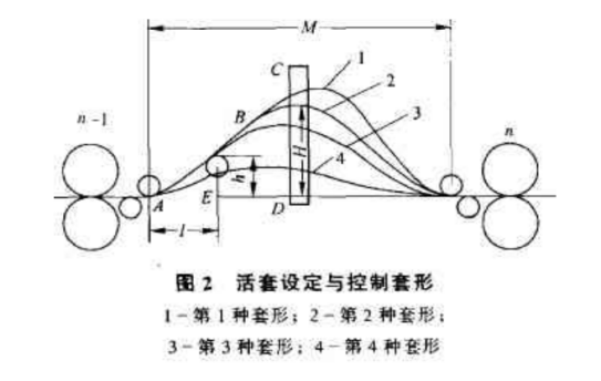
During the production process, the looper may form four sleeve shapes, as shown in the figure.
(1) The first kind of sleeve shape is due to the excessive setting of the lifting height of the looper, and the rolled piece is easy to pile up steel and swing the tail in front of the next rack, which is difficult to control.
(2) The fourth kind of sleeve shape is that the setting of the looper lifting height is too small, and the rolled piece has a large pressure on the lifting roll, which is easy to cause rapid wear of the sleeve roll and many mechanical failures; On the other hand, the rolling piece failed to realize the tension free rolling between stands, and the shape control of red billet fluctuated greatly.
(3) The second kind of sleeve shape is that the height of the looper is set properly, the looper roll works normally, the rolled piece can realize tension free rolling between stands, and the shape of the red billet is well controlled. However, if the looper roll is not taken up in time, it is also easy to cause tail flick.
(4) The third kind of sleeve shape is that the height of looper is set slightly smaller, but the looper roll can work normally, and the rolled piece can also realize tension free rolling between stands. It has good control over the shape of red billet, which is not easy to cause tail flick. Therefore, the second and third sleeve shapes can be selected according to the equipment and process conditions.
Looper accident analysis
In the actual production, it is found that there are many reasons for the loop instability or steel stacking.
1) The looper stripper roll fails to stripper for the following reasons:
① The looper scanner is faulty and cannot be detected;
② . the looper scanner is vibrated and is not aligned with the inspection port;
③ . the looper scanner lens is dirty and the detection is unstable;
④ Too much cooling water or cold fog will affect the detection sensitivity of the scanner;
⑤ Open circuit caused by poor contact of electrical circuit and other reasons, and the tripping signal cannot be sent to the solenoid valve;
⑥ The solenoid valve wire package is burnt out, and the valve cannot act;
⑦ The solenoid valve core is blocked and the valve cannot act;
⑧ . the air source is not opened or the air pipe is damaged;
⑨ The cylinder or sleeve lifting roller is mechanically stuck.
2) The reasons why the looper lifting roll does not fall may be:
① . upstream rack signal error of upstream rack;
② The solenoid valve wire package is burnt out, and the valve cannot act;
③ The cylinder or the sleeve lifting roller is suddenly blocked.
3) Analysis of steel stacking in looper area:
After the looper is pulled out of the casing, the sequence is disordered, and the looper cannot be dropped normally. The next billet is drilled into the pulling out roll, resulting in steel stacking. Solution: strengthen the maintenance of on-site detection elements, ensure the accuracy of detection signals, and pay attention to maintaining the best tapping rhythm.
Steel stacking at horizontal looper. Because the distance between two connected frames at the horizontal looper is very large, it is easy to fly steel when pulling out the looper too early, and it is easy to generate tension when pulling out the looper too late, so pay attention to the setting of the landing gear. The steel stacking at the horizontal looper before finishing rolling is often caused by the difficulty of seizing steel after finishing rolling and the long compensation time for dynamic speed drop of 19 stands. The solution is to adjust the dynamic droop compensation parameters of the 19 rack, control the tapping rhythm, and pay attention to the cooling of the horizontal looper table and prohibit breaking the steel head to take a man over the table.
4) The quantity of looper is unstable.
Generally, the looper after debugging is relatively stable. If instability occurs, do not easily stabilize the looper by modifying the height setting of the looper or increasing or decreasing the speed of the adjacent upstream rack. The stability of the looper is related to the dynamic characteristics of the speed control system of the relevant stand, the stacking and pulling relationship between rough and medium rolling, and the process adjustment in the looper area. Under normal conditions, the looper height from head to tail of the same rolled piece is allowed to change by ± 15mm. Several factors that may cause loop instability:
Electrical reasons: the detection signal of looper scanner is unstable, the lens is dirty, the cooling water and fog are too large, and there are many pieces of iron at the detection port, all of which are easy to cause the signal to sometimes fail, affecting the looper control.
Mechanical reasons: if the bearings of the backup roll and the stripper roll are burnt out, and the rotation is not flexible, resulting in uneven wear and seizure, the looper will be unstable; The eccentricity of the stripping roll or the supporting roll causes the fluctuation of the casing quantity, which generally starts from the formation of the looper and continues to the falling of the looper.
Process cause: the looper may be unstable if the guide is improperly installed or the roll gap is improperly set. The change of rolled piece temperature leads to the fluctuation of set quantity, which usually occurs after the tail or middle of rolled piece. The operator should timely notify the heating furnace to ensure the normal steel temperature. The head sleeve is too high. One possibility is that the elliptical hole is pressed down too much, the rolled piece does not match the lower round hole type inlet guide wheel, and the rolled piece resistance is too large; Another possibility is that the deviation between the end of the rolled piece and the middle ruler is too large.


Gather industry trends
 15358968703
Gather industry trends
15358968703