
15358968703
Welcome to the official mall of Cloud rolled steel !

Design of on-line vibration monitoring and fault diagnosis for main drive of hot rolling finishing mill
This paper describes the overall design, basic structure and data storage strategy of the on-line vibration monitoring and fault diagnosis system for the main drive of hot rolling finishing mill in Bayuquan branch of Angang. The system can realize the data acquisition and storage under the constant rotating speed of steel rolling, so that the spectrum analysis effect is better.
1. Introduction
The hot rolling 1580 production line of Bayuquan iron and Steel Branch of Anshan Iron and Steel Co., Ltd. was put into operation in September, 2008. Its finishing mill consists of seven mills, namely f1-f7 mill. The main transmission equipment of the unit includes 7 motors, 2 reducers (F1 and F2 rolling mills) and 7 gear bases. Since the start of the project, there have been three accidents in which the bearing of the gear base has been damaged, and one of them has caused damage to the tooth surface of the gear shaft, causing huge economic losses to the production. Therefore, it is of great significance to ensure the stable operation of the main drive equipment of the finishing mill.
At present, on-line vibration monitoring has been applied to similar units in other steel plants, but the actual application effect of some units is not ideal. There are both management and technical reasons for this. The management reason is that there is no maintenance after the system is installed, and there is no professional analysis of the data; The technical reason is that the speed change and load change conditions of the main drive equipment of hot rolling finishing mill are complex. The impact caused by the steel biting and throwing of the mill causes the equipment vibration to increase instantaneously. In addition, the vibration signal is also affected by the speed, rolling force, rolling steel type, shaft connection, working spoke vibration, etc., which brings great difficulties to the fault diagnosis of the main drive equipment of finishing mill. Therefore, it is urgent to install a set of feasible, user-friendly and accurate vibration on-line monitoring and fault diagnosis system for bearing and gear faults.
2. System structure
2.1 overall design
The main drive monitoring system of hot rolling finishing mill needs to install vibration acceleration vibration sensors on the reducer and gear base, and lead the equipment speed, process parameters (current or rolling force signals) to the data acquisition module. The acquisition module and related accessories (wiring terminal, 24V power converter, air switch, etc.) are placed in the instrument box beside the field machine, and the above signals such as vibration, speed and process parameters are introduced into the data collector through shielded cable. Each data acquisition module is connected to a wireless router nearby the machine through network cable, and a wireless router for receiving data is installed on the finishing operation console, Then connect the output data of the wireless router of the operation console to the local area network of the plant through the network cable, place a server in the secondary machine room of the main electrical room, and then transfer the data of all data collectors to the server through the local area network of the plant. The data analysis and management personnel in the plant can monitor and analyze the main drive equipment of the finishing mill on any client PC on the local area network of the plant. See Figure 1 for the specific structure. 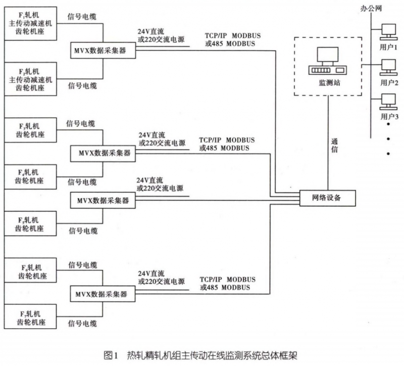 2.2 hardware
The main drive monitoring system of finish rolling has installed 36 vibration monitoring points on 2 reducers and 7 gear bases in advance, and the monitoring positions are in the horizontal direction of each gearbox bearing. The sensor is a low-frequency vibration acceleration sensor with model wt135-1d, sensitivity of 500mv/g, frequency response range of 0.1-10khz. The installation method is permanent installation, that is, a 6-8mm deep M6 hole is machined on the equipment surface, and then the sensor is screwed and connected with double head screws. Considering that the sensor is a side outlet line, an adjusting gasket is installed at the bottom of each screw to make the side outlet cables of the sensor orderly arranged after tightening. In order to improve the accuracy of vibration analysis, the monitoring system also installed seven speed sensors on the input shaft side of the gear base of f1-f7 rolling mill. Since the vibration of the main drive equipment of the finishing mill is greatly affected by the real-time load, it is necessary to introduce process parameters to distinguish the status of steel rolling and idling. The current signal can truly reflect the change of load, but the introduction of current signal may cause interference, which is slightly more risky than the introduction of switching value rolling force signal. Therefore, the rolling force signal is connected to the data collector as process parameters together with the above vibration and speed signals, To accurately distinguish the real-time dynamic change causes of equipment vibration value.
The data collector adopts the MVx module of 01db company in France. This module has a built-in CPU. All collected data are processed locally. Only the calculation results are uploaded to the server for data storage and browsing. It also has an automatic diagnosis function (automatically extracting fault symptoms and adding judgment). It can collect 24 channels of vibration, current, speed and various process parameters in real time and in parallel. The channel expansion is more convenient. When the equipment is in the process of starting or stopping, the monitoring module can automatically change the acquisition mode to transient analysis, and can remotely reset the MVx.
2.3 software
The system software adopts browser version of state monitoring nest and vibration analysis xpr300. Nest is the state monitoring software, including the vibration characteristic value of each measuring point. The system can constantly check and update the alarm status of the current value of each measuring point. If an alarm occurs, the corresponding identification changes color and flashes, so that the point inspection, patrol inspection and management personnel at all levels can timely master the operation status of the equipment. Xpr300 is the core of monitoring data, analysis and diagnosis. It has powerful data analysis functions, including time domain waveform, amplitude spectrum, phase spectrum, link spectrum, cepstrum, Bode diagram, Nyquest diagram waterfall diagram and axis trajectory. It can automatically check and judge the operation status of the unit from a large number of collected data, and will automatically give alarm information if abnormal or defective units are found. Both software adopt Oracle large-scale relational database, which can manage and store various types of data. The software can directly communicate with SAP and Maximo asset management software, and provide OPC interface to exchange data with other asset management systems.
3. Data storage settings
3.1 rolling conditions
The real-time collection of monitoring data is relatively easy to achieve, but the storage and analysis of data is more meaningful for the accuracy of equipment fault diagnosis. The operation condition of the main drive equipment of the finishing mill is an empty pass - Steel biting - steel rolling - Steel throwing - empty pass, which is a working cycle. In the rolling process of the hot tandem rolling production line, in order to ensure equal metal flow per second and constant exit strip temperature, the whole rolling process is variable speed rolling. Generally, when the hot coil box is put into use, it is reduced speed rolling, and when the hot coil box is not put into use, it is increased speed rolling. Take the hot coil box not put into use as an example. After the threading of the whole finishing mill, the main drive equipment starts to increase the speed for rolling. After the coiler establishes the tension, the speed is basically constant. Then, the speed is reduced for rolling, and finally the steel is thrown. Whether the speed is increased or reduced, there is a period of constant speed. According to the statistics of the actual situation of each steel type, the rolling time of each steel is about 75s, the time from F7 mill to coiler is about 25s, and the throwing time is about 15s, The constant speed time is about 30s.
3.2 storage mode
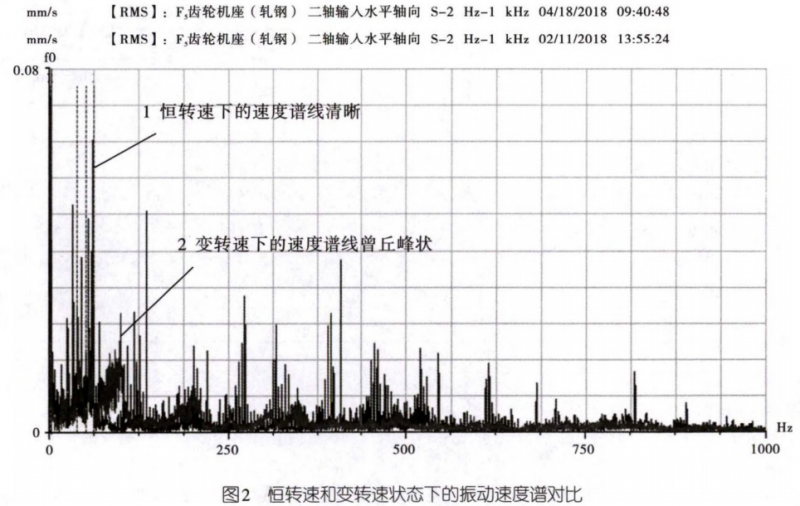
The time domain average method is usually used for vibration analysis of variable speed equipment. This method can retain the periodic components related to gear faults and remove the interference of other non periodic components and noise, so as to improve the signal-to-noise ratio. Although this method strengthens the effect of gear fault diagnosis, it filters the fault signal of rolling bearing, that is, it can not effectively analyze the rolling bearing fault. Therefore, considering the variable speed and load conditions of the finishing mill, it will be better to store the vibration data during the period when the above speed is basically constant. Taking the off-line monitoring data under the rolling state as an example, the spectrum line 1 in Figure 2 shows the speed spectrum when the rotating speed is constant under the rolling state (tension is established between the coiler and the finishing mill), and the spectrum line is clear, while the spectrum line 2 shows the speed spectrum when the speed is increased or decreased during the rolling process, and the spectrum line has a peak shape, so the spectrum analysis effect is not good.
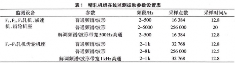
In this system, rolling force signal is introduced into each rolling mill. Considering that it is more effective to save the vibration data at constant speed, the current mode of vibration data storage is to trigger and delay the rolling force signal for each rolling mill, that is, after the rolling force signal is triggered, the rolling mill delays 35, 38, 40, 41, 42, 43 and 44s respectively to start storage. See Table 1 for the data sampling points, analysis frequency and demodulation bandwidth parameters stored in each rolling mill. It can be seen from table 1 that the storage length of the data is 12.5-20s, which meets the constant speed time for the aforementioned coiler to establish tension. In the future, the signal that the coiler establishes tension will also be introduced into the system to further ensure that the vibration data within the constant speed period can be accurately collected and stored.
4. Vibration standard
According to the provisions of gbft6075.3-2011 vibration standard, the alarm value of the effective value of the vibration speed of the hot rolling finishing mill shall be 0.25 times higher than the steady-state baseline value determined by experience (the representative and repeatable normal value of the equipment during steady-state operation, which is generally obtained from the statistical average value measured many times during the previous normal operation of the equipment), and generally shall not exceed 1.25 times the upper limit value of region B. The upper limit of zone B is 4.5mm/s. The shutdown value is the maximum vibration that the equipment can withstand. It is a fixed value and usually does not exceed 1.25 times the upper limit value of area C of 7.1mm/s, i.e. 8.875mm/s.
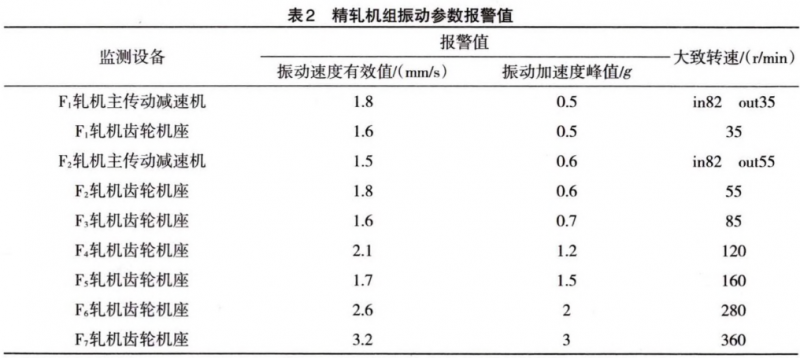
Generally, the fault of rolling bearings and gears will cause the vibration acceleration value in the high frequency band to increase significantly. However, there is no relevant standard for the vibration acceleration value in the domestic and foreign vibration standards at present. Based on the field experience, the vibration standards of each equipment of the finishing mill are shown in Table 2.
5. Fault diagnosis example
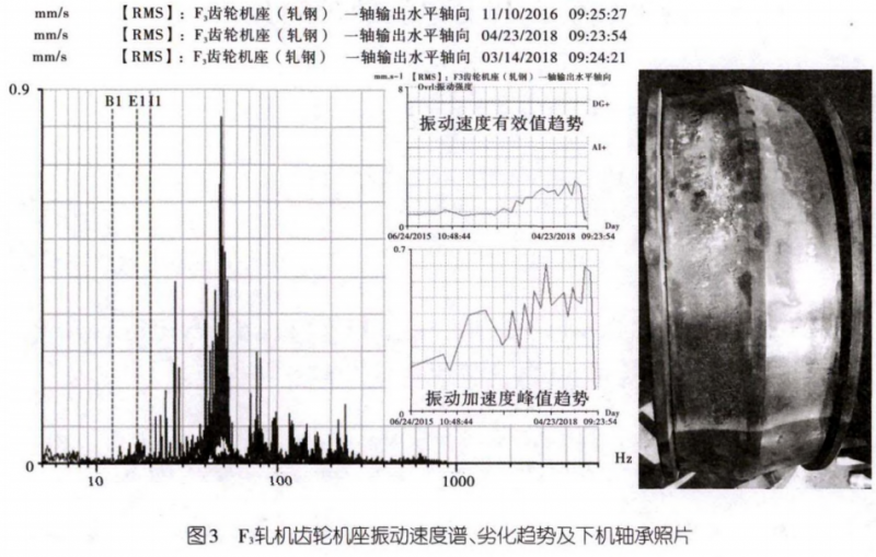
From june2015 to april2018, the vibration of the lower measuring point at the outlet of F3 gear base for hot rolling finishing rolling showed a gradual deterioration trend, and the vibration velocity spectrum had obvious bearing inner race fault frequency and frequency doubling, and both were accompanied by power frequency sidebands. Theoretically, the fatigue spalling in the raceway of the bearing inner ring can be maintained for a long time, which may cause pitting on the rolling element, and may lead to rapid damage to the cage in the later stage. During April, the gear base of the code rolling mill was replaced on site. There was a large area of surface metal spalling on the bearing inner ring and obvious pitting corrosion on the rolling element. After replacing the gear base, the vibration value decreased from 2.3mm/s to 0.4mm/s, and the peak force port speed decreased from 0.6g to 0.05g. See Figure 3 for details.
6. Conclusion
The on-line monitoring and fault diagnosis system of hot rolling finishing mill integrates signal processing technology, computer technology and network technology, and can accurately diagnose the faults of rolling bearings and gears of main transmission equipment. The data storage and analysis of the system are based on the different operating states of the equipment, realizing the distinction and comparison of the data under the two different working conditions of steel rolling and air passing. The data collection and storage under the steel rolling state come from the constant speed period when the tension of the coiler is established, and its spectrum is easier to analyze and diagnose. The data collection and storage strategy of this system can be used for reference by peers.


Gather industry trends
 15358968703
Gather industry trends
15358968703