
15358968703
Welcome to the official mall of Cloud rolled steel !

The utility model relates to a horizontal switching mill for rod finishing rolling
The invention relates to the technical field of bar rolling, in particular to a horizontal switching mill for bar finishing rolling.
In the prior art, the horizontal vertical conversion of the mill generally has the following three ways: (1) The Premini type uses two above-ground hydraulic cylinders to drive the steel frame with the rolling mill body to rotate 90° on the C-frame to realize the horizontal rolling mill to the vertical state, and the main motor is connected through the bevel gear box and the long shaft to the vertical mill transmission gear box, and the horizontal vertical state is driven by a main motor; (2) Danieli type uses an underground hydraulic cylinder to drive the steel frame with the rolling mill body to rotate 90° on the C-frame to realize the horizontal rolling mill to the vertical state. The main motor is connected with the transmission gear box of the vertical rolling mill through the bevel gear box and the long shaft, and the horizontal vertical state is driven by a main motor; (3) A compound gear box with three output shafts respectively outputs torque to the horizontal mill and the vertical mill. The vertical output is converted to the vertical gear box through the bevel gear box and then distributed to the mill. The horizontal mode is that the two output shafts on the compound gear box and the rolling mill are connected by two long universal-joint shafts, and the horizontal state is driven by a main motor.
Types (1) and (2) have high requirements for equipment installation and manufacturing accuracy. When the mill is in a horizontal state, the main motor shaft and the transmission gear box input shaft are required to be concentric; When the mill is in a vertical state, the main motor shaft is required to be concentric with the input shaft of the bevel gearbox. After long-term use, due to factors such as frame deformation, concentric adjustment is difficult. In addition, as the main supporting part of the rotation, the guide groove wear and the deformation of the C-frame increase the resistance of the rotation process, and the rotation is time-consuming and laborious, and the vibration of the rolling mill is large. Due to the rotation deeper into the ground, up to -3m, resulting in a deeper design of the gutter. Type (3) Although there is no rotation process, it is very inconvenient to install and repair because the reversing bevel gear box and its long axis and the universal joint shaft of the horizontal mill are all under the platform foundation of the vertical mill. In addition, because the compound gear box is installed outside the base platform of the vertical mill, the universal joint shaft of the horizontal mill is relatively long, and the vibration of the mill is large when running at high speed.
The technical problem to be solved by the invention is to provide a vertical switching mill for rod finishing rolling.
The rolling mill includes a vertical rolling mill system, a horizontal rolling mill system, a rolling mill body, a gearbox dynamic base, a horizontal static base, a pin hydraulic cylinder, a vertical rolling mill roll changing trolley and a transverse hydraulic cylinder. Among them, the vertical rolling mill system includes a main motor, a coupling, a gearbox and a universal joint shaft, and the vertical rolling mill system is installed on a concrete platform. The vertical rolling mill system is connected with the rolling mill body through the universal joint shaft I, the rolling mill body is installed on the horizontal static base through the rolling mill body dynamic base, the horizontal rolling mill system includes the main motor II, the coupling II, the gear box II and the universal joint shaft II, the horizontal rolling mill system is installed on the gear box dynamic base, the rolling mill body dynamic base and the gear box dynamic base are connected through the latch hydraulic cylinder. The horizontal rolling mill system connects the rolling mill body by two universal-joint axes.
The concrete platform foundation for installing the vertical rolling mill system is located above the rolling mill body.
The horizontal rolling mill system is installed on the moving base of the gear box and is locked by hydraulic cylinder.
The roller changing trolley of vertical mill is secure in the horizontal static base and can be lifted away by the crane.
The universal-joint shaft II and gearbox II can be pulled out by the transverse hydraulic cylinder.
When the horizontal rolling mill system changes the pass type, the coupling between the main motor 2 and the gear box 2 is telescopic, which meets the requirements of the transverse travel of the rolling mill. The universal joint shaft 2 adopts the crosshead joint shaft with short length to ensure the smooth running at high speed.
The vertical state of the mill is driven by two main motors respectively, and the electric control system is shared with one set for automatic switching. The transmission system of the horizontal rolling mill system (gear box and universal joint shaft) is integrated into the concrete platform foundation of the vertical rolling mill, and it is easy to pull out for maintenance. The gear box II and the universal joint shaft II of the horizontal rolling mill system are installed on a moving base and are locked by a hydraulic cylinder, which is similar to the installation of the rolling mill body. The moving base of the gear box and the moving base of the rolling mill are connected through a pair of pin hydraulic cylinders to ensure that the gear box, the universal joint shaft and the rolling mill move together when the horizontal rolling mill changes the pass shape. The horizontal rolling mill body, universal joint shaft and gear box are installed on a large static base through a moving base. The width of the gear box is limited by a vertical split structure. The gear box and universal joint shaft are located in the space directly below the platform foundation of the vertical rolling mill system, and the main motor is located outside the platform foundation of the vertical rolling mill. When the roll change operation, the latch hydraulic cylinder is loosened, and the rolling machine base with the rolling mill body is removed from the rolling line by the crane. When the gear box and the universal joint shaft are repaired or installed, the transverse hydraulic cylinder and the gear box moving base can be manually connected, and the universal joint shaft and the gear box can be moved out of the platform base range of the vertical mill and pulled to the position where the crane can be lifted off the operating side. The structure of the vertical rolling mill system remains the same as the conventional design, and adopts the concrete platform foundation design, which can run smoothly at high speed. The vertical roll changing trolley is placed in the static base of the horizontal rolling mill. When the horizontal rolling mill mode is adopted, the trolley is lifted away by the crane. The rolling mill body and its moving base are used in both horizontal and vertical modes.
The beneficial effects of the technical scheme of the invention are as follows:
Compared with the prior art, the structure design of the horizontal vertical switching mill for rod finishing rolling can be conveniently switched between two modes of the horizontal vertical mill according to the structure, the switching time is almost the same as the roll changing time, the process is simple, the maintenance is convenient, and it is suitable for large-scale production, so it can effectively improve the production efficiency. In the structural design, both horizontal mode and vertical mode can ensure the smooth operation of the rolling mill at high speed and guarantee the dimensional accuracy of the bar products. In addition, because of the shallow rolling mill foundation and shallow ditch design, it is beneficial to the investment and construction of the water treatment system of the bar production line arranged on the ground.
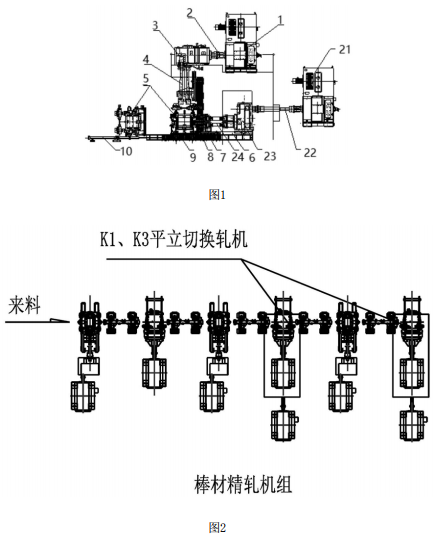
FIG. 1 is a structural diagram of a horizontal and vertical switching mill for rod finishing rolling.
FIG. 2 is an arrangement diagram of a horizontal and vertical switching mill for rod finishing rolling of the invention.
Among them: 1- main motor 1, 2- coupling 1, 3- gear box 1, 4- universal joint shaft 1, 5- rolling mill body, 6- gear box dynamic base, 7- horizontal static base, 8- pin hydraulic cylinder, 9- vertical rolling mill roll change car, 10- horizontal hydraulic cylinder; 21- Main motor 2, 22- coupling 2, 23- gear box 2, 24- universal joint shaft 2.
In order to make the technical problems, technical schemes and advantages to be solved by the invention more clear, the following will be described in detail in combination with the attached drawings and embodied embodiments.
The invention provides a horizontal switching mill for rod finishing rolling.
As shown in Figure 1, the rolling mill comprises a main motor 1, a main motor 2 21, a coupling 2, a coupling 2 22, a gear box 3, a gear box 2 23, a universal joint shaft 4, a universal joint shaft 2 24, a rolling mill body 5, a gear box dynamic base 6, a horizontal static base 7, a pin hydraulic cylinder 8, a vertical rolling mill roll changing trolley 9 and a transverse hydraulic cylinder 10, among which, Main motor 1, coupling 2, gear box 3 and universal joint shaft 4 constitute a vertical rolling mill system, the vertical rolling mill system is installed on the concrete platform, the vertical rolling mill system is connected to the rolling mill body 5 through the universal joint shaft 4, the rolling mill body 5 is installed on the horizontal static base 7 through the rolling mill body dynamic base. Main motor No. 21, coupling No. 22, gear box No. 23 and universal joint shaft No. 24 constitute a horizontal rolling mill system. The horizontal rolling mill system is mounted on the gear box dynamic base 6, and the horizontal rolling mill system is connected to the rolling mill body 5 through the universal joint shaft No. 24.
The actual operation process of the mill is as follows:
Installation: The vertical rolling mill system is conventionally-designed and installed on the concrete platform foundation, and the entire installation process is within the lifting range of the crane. When the horizontal rolling mill system is installed, the main motor II 21 and the coupling II 22 with expansion are first installed by the crane. Then the horizontal static base 7 and the transverse hydraulic cylinder 10, and finally the gear box 2 23 and the universal joint shaft 2 24 are installed on the gear box dynamic base 6, pushed into the concrete platform foundation of the vertical rolling mill system by the transverse hydraulic cylinder 10, connected the coupling and the oil pipe, the transverse hydraulic cylinder 10 and the gear box dynamic base 6 are separated manually, and returned to the original position. Then the rolling mill installed on the moving base outside the line is lifted to the horizontal static base 7 by the crane, and the rolling motor base and the transverse hydraulic cylinder 10 are manually connected, and the transverse hydraulic cylinder 10 is pushed into the rolling line and connected with the universal joint shaft. The rolling machine base and gear box dynamic base 6 are connected through the latch hydraulic cylinder 8. Finally, the rolling machine base and gear box dynamic base 6 are locked with the static base through the hydraulic cylinder to complete the installation process of the horizontal rolling mill system. If the horizontal mill mode is used, the vertical mill roll changing trolley 9 is lifted by the crane; if the vertical mill mode is used, the vertical mill roll changing trolley 9 is located outside the rolling line so as not to affect the lifting of the vertical mill.
Roll change: When the vertical rolling mill changes, the rolling mill is at a high position first. The vertical rolling mill roll change trolley 9 is moved from the rolling line to the rolling line by moving the hydraulic cylinder 10 horizontally, the rolling mill lock cylinder is opened, the rolling mill is put on the vertical rolling mill roll change trolley 9, and the rolling line is pulled out by the horizontal hydraulic cylinder 10. When the horizontal rolling mill is changing rolls, the latch hydraulic cylinder 8 connecting the two moving bases is opened, the rolling mill locking cylinder is opened, and the rolling line is pulled out by the transverse hydraulic cylinder 10. The installation procedure for the new mill is reversed.
Change the pass: When the vertical rolling mill changes the pass, the rolling mill lock cylinder is opened, the rolling mill moves up and down, and then locks. When the horizontal rolling mill changes the pass shape, the rolling mill and gearbox locking cylinder are opened, the rolling mill and the universal joint shaft and gearbox are moved left and right together, and then locked.
Overhaul: The opposite of the installation process.
FIG. 2 shows the process plane layout of the production line actually applied by the invention. The bar finishing mill group is composed of 6 mills, and the layout type is flat - vertical - flat - flat/vertical - flat - flat/vertical, K1 and K3 mills adopt the horizontal switching mill, and when the multi-line scuttling rolling process is adopted, K1 and K3 mills adopt the horizontal mode. When the single line rolling process is used, the K1 and K3 mills are in vertical mode.
At present, there are more than 300 bar production lines in China, with an annual output of more than 200 million tons. The invention is suitable for reforming the existing rolling mill, and can also be used in a new bar production line, and has a broad application prospect.
The above is the preferred embodiment of the invention, and it should be noted that for ordinary technicians in the technical field, a number of improvements and refinements can be made without deviating from the principle of the invention, and these improvements and refinements shall also be considered as the scope of protection of the invention.


Gather industry trends
 15358968703
Gather industry trends
15358968703