
15358968703
Welcome to the official mall of Cloud rolled steel !

Analysis and application of rod loop control principle
Abstract.:The principle of looper control and the function of system control are described. In view of the fact that the running condition of the looper directly affects the quality of the product and the efficiency of the production, the frequent failure of the looper in the commissioning and application process of the special rod factory of Baosteel Special Steel Shaoguan Company was analyzed from the mechanical and electrical aspects, and the optimization measures were taken, and good results were obtained.
The loop is an important auxiliary equipment in the continuous rolling production line, which can be used as a buffer link when the speed between the frames is not coordinated, and it is also a means to control the fluctuation of the dimensional accuracy of the rolled parts affected by the dynamic speed change between the frames during the rolling process, so as to achieve no torsion and no tension. Looper control system is composed of mechanical and electrical fields, production debugging and daily maintenance of looper control system is the key to improve the rod line production rate, but because it spans the two fields of machinery and electricity, there are some difficulties in daily maintenance and fault handling.
The special rod continuous rolling line of Baosteel Shaoguan Company has 6 loops, of which 4 loops are distributed in finishing mill group and 2 loops are distributed in reducing sizing unit. Because of the small cross-sectional area of rolled parts passing through this area, looping control is used to ensure the transverse dimensional accuracy of rolled parts, and to realize the tension-free control rolling of finishing mill and reducing sizing unit. However, in the actual operation, the looper can not meet the process requirements due to various factors, and the pile steel caused by the looper failure also has a certain impact on the production. How to improve the control precision of looper and optimize the performance of control system is the key technology.
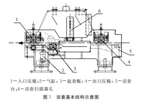
The basic structure of looper is mainly composed of looper table, lifting roller, pneumatic system, looper scanner, looper adjusting system, etc. The sleeve roller plays the role of guiding and supporting the rolled piece. The sleeve roller is driven by the cylinder, and the cylinder of the sleeve roller is controlled by the double solenoid valve, as shown in Figure 1.
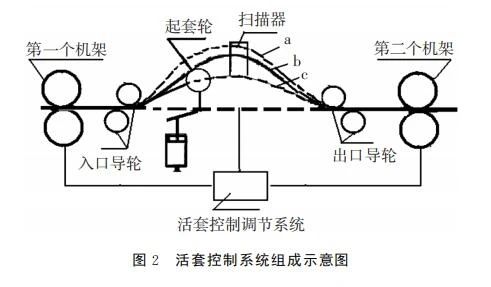
Each looper control system is mainly composed of lifting roller, pneumatic control system, looper scanner, looper lift and fall logic, sequential control and loop control system. A single looper control system can only be used with the speed control system of the rolling mill connected to it. When all the looping control systems are coupled together to form a closed-loop control system through the cascade speed control system, the looping control system can automatically adjust the speed of each continuous mill to ensure that the second flow rate is equal, and improve the quality of rolled parts and rolling efficiency. The automatic control of looping is accomplished on the basis of measuring the curved rolling pieces formed by the connected frames. The arc curve rolled piece between the frame is guided by the lifting roller device through the logic control system, so that the rolled piece forms a looper on the looper table, and the looper scanner is used to measure the looper quantity to measure the looper length indirectly. The adjustment range of the looper and the storage capacity of the looper are limited. When the speed match of the adjacent rack is unreasonable or other reasons make the deviation of the looper too large, the automatic control system of the looper is too late or unable to adjust, which will cause the phenomenon of stacking steel or breaking rolled parts. Therefore, the formation of the trope is achieved by changing the rack speed related to the looper. The arc curve height of the rolled piece is measured indirectly by the looper scanner. The scanner compares the actual value of the measured trope with the set value according to the principle of linear relationship between its output and the trope, and then according to its deviation, The cascade speed control system guides and automatically reverses all mill speeds upstream. That is to say, during the whole loop control stage, the volume of the loop is adjusted by correcting the speed of the upstream mill by a cascade speed regulating system. The arc curve height of the rolled piece is equal to the integral of the difference between the rolling piece speed at the entrance of the loop and the rolling piece speed at the exit. When the inlet speed is greater than the outlet speed, the sleeve amount will gradually increase, as shown in Figure 2 a; On the contrary, the amount of nesting gradually decreases, as shown in Figure 2 (c). When equal, the trope remains unchanged, as shown in Figure 2 b. The composition diagram of the looper control system is shown in Figure 2.
The lifting and falling process of the jacking roller is performed by the cylinder, and this execution process is automatically controlled by the looper pneumatic system regulator, which adopts three closed-loop control loops v1, v2 and v3. As shown in Figure 3, the lifting and falling process of the jacking roller is performed by the cylinder, and this execution process is automatically controlled by the looper pneumatic system regulator. The looper pneumatic system adopts three closed-loop control loops v1, v2 and v3, as shown in Figure 3
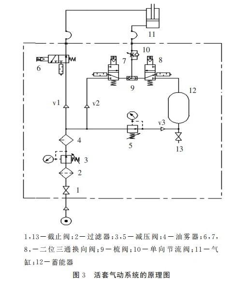
When the head of the rolling piece is bitten into the downstream frame of the looper, the looper pneumatic system needs a delay time after receiving the jacking command to establish the required air pressure to form the initial sleeve amount. If the jacking roll moves too early or too late, it is easy to cause the rolling piece to pile steel, which requires precise control of the delay time of the jacking roll action. When the looper pneumatic system receives the jacking instruction, the gas valves 6, 7 and 8 on the pipeline v1 and v2 get power, and the gas source passes through the valve 7, 9 and 10 into the rodless chamber 11 of the cylinder, and the gas with the rod chamber of the cylinder is discharged from the gas valve 6 on the pipeline v1, the piston rod is extended, and the jacking roller is lifted. In the initial stage of jacking, it is beneficial to use high pressure gas supply in pipeline for smooth jacking of looper. After the looper completes the initial sleeve volume and the sleeve roller reaches the maximum sleeve volume position for 1s, the gas valve 7 on pipe v2 loses power, and the gas valve 8 on pipe v3 independently supplies gas to support the sleeve roller. The gas source supporting the sleeve roller is provided by the constant pressure gas of pressure regulator 5 and accumulator 12 of pipe v3. When the looper scanner detects that the looper height exceeds or falls below the set value, the looper regulator adjusts the frame speed proportionally to maintain the looper volume through a cascade governing system based on the deviation of the measurement of the looper height. In the adjustment process, the air source pressure is not affected by the influence of the tube v1 pressure, which ensures that the set value of the sleeve is unchanged, the second flow balance between the frame is achieved, and the sleeve roller will not shake because of the insufficient support force, which greatly reduces the possibility of steel pile caused by the pressure problem. When the end of the rolling piece is close to the front frame of the looper, the looper height given signal will gradually reduce the amount of the looper. With the control system receiving the looper instruction, the gas valves 7 and 8 on the pipeline v2 and v3 will lose power at the same time, and the gas in the rodless cavity will enter the rod chamber of the cylinder through the valve 6 on the pipeline v1, and the gas in the rodless chamber will be discharged by the unidirectional throttle valve 10 installed on the pipeline v2 through the valve 7 and 8. The lifting roll is pressed down, and the unidirectional throttle 10 is properly adjusted when set to provide a certain resistance to prevent too fast falling. In this way, a process of rising and falling is completed. Because the loop control system uses a closed loop control loop, the accumulator only maintains a certain amount of looping under no tension, and the amount of different specifications of rolled parts can also be adjusted by adjusting the pressure of the reducing valve 5 to keep the rolled parts in a tension-free state.
At the beginning of commissioning and use, there are many factors affecting the instability of looper control in the production practice. The main reasons are analyzed and improved, such as the parameters of looper scanner, the accuracy of detection signal and the non-action of sleeve roller. The looper scanner is affected by environmental factors such as more water vapor, large dust and rolling temperature, which is easy to blur the perspective mirror of the looper scanner, affecting the sensitivity of the scanner detection. The maintenance of the looper height scanner is extremely important, so it is necessary to test and adjust the looper height scanner regularly, improve the accuracy and sensitivity of the scanner, and strengthen daily spot inspection and maintenance. The main detection items are whether the actual height of the looper is consistent with the height value of the looper scanner, and the sensitivity of the signal is verified, and should be replaced in time if necessary. At the same time, considering the stability of the looper and the dynamic characteristics of the speed control system of the relevant frame and the relationship between the pile pulling of coarse and medium rolling and the process adjustment of the looper area, the range setting of the looper scanner is adjusted to allow the looper to have a ±20mm sleeve change from the head to the tail of the same rolled piece. In this case, when the looper scanner detects that the actual height is beyond the original set value of ±20mm, the looper control adjustment system works to stabilize it within the range. Of course, in the actual application process, due to the equipment or rolling specifications, some looping can not be put into, but in order to make the cascade speed control better, special treatment is done in the program, the looping can be freely selected and combined, so that the best control can be achieved. The reason for the failure of the sleeve roller is that the cylinder does not move, which is caused by two factors: electrical cause and pneumatic cause. Whether the cause is electrical or pneumatic is difficult to determine immediately, and can only be confirmed by examining the electrical and pneumatic components one by one.
(1) Electrical control system failure. Due to site vibration, wiring is not strong caused by loose wiring or too much dust resulting in poor contact, the up and down signal is not sent in time or is not sent to the corresponding solenoid valve, so that the site signal is sometimes no, resulting in the reversing valve action confusion, resulting in adjustment oscillation phenomenon; Second, the equipment is damp or water and other reasons to short-circuit the power line connection, so that the signal received by the solenoid valve is lower than the signal of the solenoid valve, resulting in the solenoid valve can not be fully opened or fully closed, affecting the electromagnetic directional valve does not operate. For the above reason analysis, in order to facilitate the on-line judgment of the looper failure cause, first of all, the electric control signal indicator screen is specially added above the valve plate to judge whether it is electrical reason, which is convenient to narrow the fault identification range; At the same time, the application of the valve installation and selection of the indicator light, which can be more intuitive to reflect the control signal indication status, if in the event of a failure, the valve indicator light is on, indicating that the control system has issued instructions, the possibility of failure of electronic components is less, the possibility of failure of pneumatic components is greater. If the indicator light on a certain line or air valve is not bright, it indicates that the electronic control element on the corresponding circuit is faulty, indicating the direction for finding and troubleshooting.
(2) Pneumatic component failure. The failure of a valve in the pneumatic circuit will cause the failure of the jacking cylinder. When the lifting cylinder does not act or the air valve appears stuck, the valve body of the reversing valve has been disassembly and checked for many times, and it is found that there is a gap between the valve core and the seat when the reversing valve is fully closed, resulting in the leakage of the air source when the valve is fully closed, and the controlled parameters are difficult to stabilize; Due to the original design of two-position three-way valve manufactured in China, the main valve adopts piston cone end face and cutoff soft seal, and the piston is equipped with O-ring, which requires a large air source thrust to push the valve core to move; Third, the valve core is scarred by welding slag, rust, or water vapor (residue) and other scratches and corrosion in the air source pipeline, the seal between the valve seat and the valve body is damaged, and the valve one-way action or even immobility is caused by large friction, so it is easy to produce blocking phenomenon, which belongs to the valve's own defects leading to low stability and cannot adapt to the lofting pneumatic system with fast response and high frequency. Therefore, the air valve modification selects the imported two-three-way electronically controlled reversing valve instead of the domestic reversing valve, the valve adopts the slide valve structure and balanced design, which is not affected by the change of air pressure; Large electromagnetic force; There is no other oil seal on the spool, the friction is small, no lubrication is required, and the reliability and sensitivity meet the field requirements.
Looper control is the key technology to determine the quality of rolling parts. Through the installation, debugging and production practice of rod and wire looper, the equipment is further optimized and improved according to local conditions on the basis of existing equipment, and the performance of looper control system is constantly improved to meet the needs of rolling production rhythm. Even if there is a looper fault, it can be more convenient to find the cause, greatly reduce the time of troubleshooting, and ensure the further increase of the output of the rod line.


Gather industry trends
 15358968703
Gather industry trends
15358968703