
15358968703
Welcome to the official mall of Cloud rolled steel !

[technology] summary of key points for field assembly of oversized four row cylindrical bearings
1、 Structural performance
1.1 performance introduction
As a typical rolling mill roll diameter bearing, the four row cylindrical roller bearing has parts that can be separated from each other with high precision, and parts can be interchanged. It is very convenient to install, disassemble and clean. In particular, the oversized fcdp structure can provide the maximum radial bearing capacity within the given radial installation space, and has a low friction coefficient. Almost all types of support rollers for wide four and six high rolling mills are fcdp four row cylindrical roller bearings, The outer ring and the rolling element are installed in the bearing housing, and the inner ring interference is installed on the roll diameter of the roll.
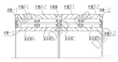
1.2 bearing structure
Bearing composition: two side retaining rings, four rows of rolling elements and cage components, one intermediate spacer ring and two inner rings. During installation, ensure that the corresponding outer ring raceway of each row of rolling elements and prevent parts from interference and collision. This requires that the installation process must be standardized to ensure the normal operation of the bearing.
2、 Assembly process
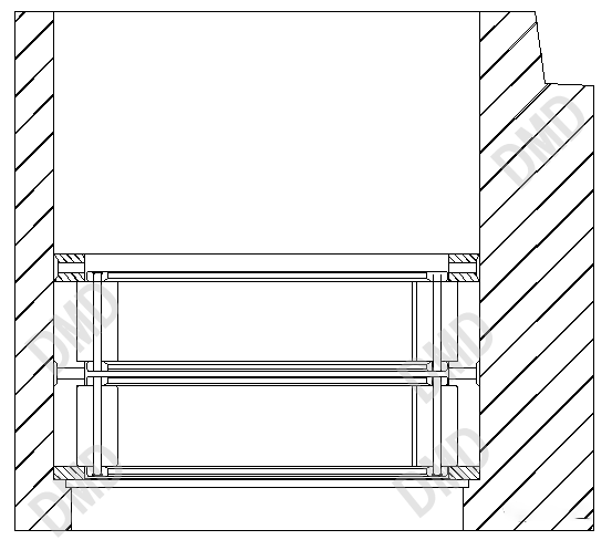
2.1 step 1
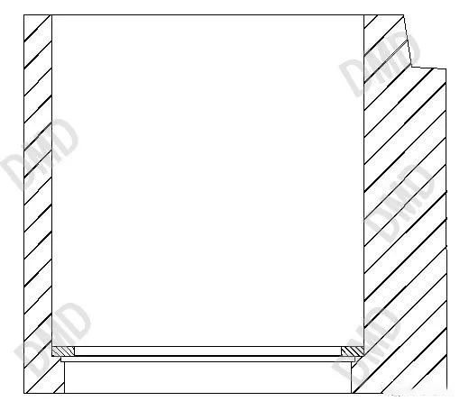
The bearing box shall be leveled, the hole diameter in the box shall be cleaned, the sharp corner burrs at the hole diameter and steps shall be removed, and the hole diameter shall be coated with clean lubricating oil to ensure the smooth installation and sliding of the bearing and protect the box.
First, put in the retaining ring-1. Two people are required to work together when putting it in. The retaining ring-1 can be released when it is placed about 50mm away from the lower step of the box. Do not let go directly at the top of the box hole. If the retaining ring-1 falls and tilts to the hole diameter of the box, it will jam and interfere.
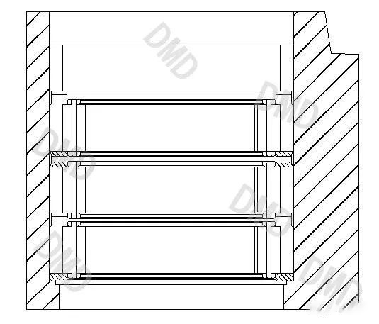
2.2 step 2
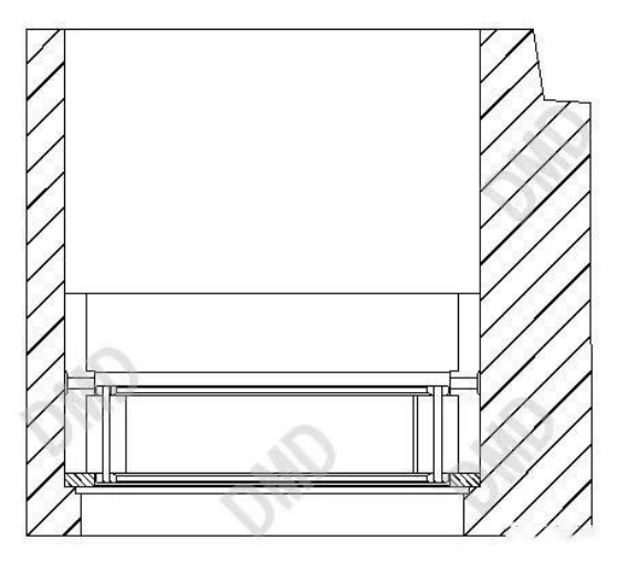
At the same time, hoist and place the rolling element a and the corresponding outer ring A. do not put the rolling element a first and then the outer ring a to prevent the outer ring from sliding and causing collision damage to the roller a.
2.3 step 3
When hoisting and placing the rolling element B, the hoisting level must be ensured to prevent the rolling element B from large inclination (more than 10mm) and scratching the surface of the rolling element and the raceway of outer ring A2 when sliding.
2.4 step 4
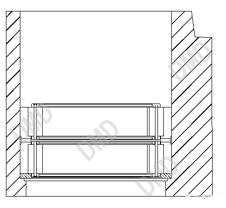
When placing the middle retaining ring, two people are also required to work together. When the middle retaining ring is placed about 50mm away from the A2 end face of the outer ring, it can be released. It is prohibited to release the middle retaining ring directly on the top of the box hole, and the middle retaining ring falls and tilts to the box hole, blocking interference occurs.
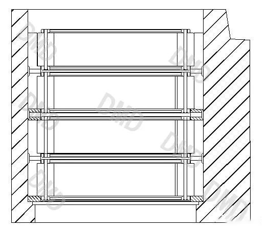
2.5 step 5
Similarly, in step 2, the rolling element C and the corresponding outer ring B shall be hoisted and placed at the same time. Do not put the rolling element C first and then the outer ring B to prevent the outer ring from sliding and causing collision damage to the roller C.
2.6 step 6
Similarly, in step 3, the rolling element D shall be hoisted and put in, and the hoisting level shall be ensured to prevent the rolling element d from large inclination (more than 10mm) and scratching the surface of the rolling element and the raceway of outer ring B2 during sliding.
2.7 step 7
Put in the retaining ring-2. Before putting it in, knock the end face of the outer ring B2 with a copper bar to check and ensure that each end face of the bearing is connected tightly. Then put in the retaining ring-2. After that, lock the gland. Measure the gap between the gland extension and the retaining ring-2 with a depth gauge and a feeler gauge, and select appropriate adjusting shims to ensure that the gap between the gland extension and the retaining ring-2 is not greater than 0.05mm after the gland is locked.
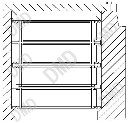
2.8 step 8
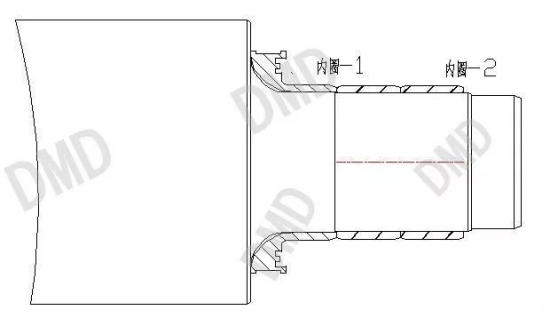
The inner ring is installed. The inner ring is heated to 80-95c ° by the electromagnetic induction heater. Before installation, ensure that the shaft diameter is clean and that the sharp corners and burrs of the shaft shoulder and shaft diameter are treated.
First install the inner ring-1. After installation, ensure that the end face of the inner ring is close to the end face of the shaft shoulder. Then install the inner ring-2. Finally, ensure that the inner ring-1, the inner ring-2 and the end face of the shaft shoulder fit each other.


Gather industry trends
 15358968703
Gather industry trends
15358968703